
The server part of the pilot application runs on the TINI hardware. The server handles connections from clients on the TCP/IP network and processes requests for information regarding status of the CAN bus or requests to route CAN data frames between client application and the CAN bus. To protect theTINI against processing overload, the number of simultaneous clients connected to the server can be limited. Also, a form of authentication is used to identify the client and to limit routing of CAN frames to a client that connects to the server. Fig. 3 depicts the static UML class diagram of the server classes.
The CanMonitorServer class contains the 'main' application entry point. This class initializes the singleton class CanBusInterface and waits for a client to connect over a TCP/IP connection. When a client connects, a new instance of the CanMonitorServer is started and a CanStatusClient and CanFramesConnection are instantiated. The client can start or stop forwarding of CAN frames over the TCP/IP connection by commands issued to the CanStatusClient. When CAN frame forwarding is enabled, the instances of CanFramesConnection and CanFramesClient are responsible for respectively transmission of CAN frames to the client or reception of CAN frames from the client. A CAN frame is transmitted in serialized form through a data stream (java.io classes DataInputStream and DataOutputStream are supported on the TINI java virtual machine implementation). The classes CanBus and CanFrame in fig. 3 are part of the TINI comm package supplied by Dallas Semiconductors. The java code of the Can Monitor server classes is listed in appendix A. Figure 4 shows the system log of a session in which a client connects two times to the Can Monitor server application on the TINI.
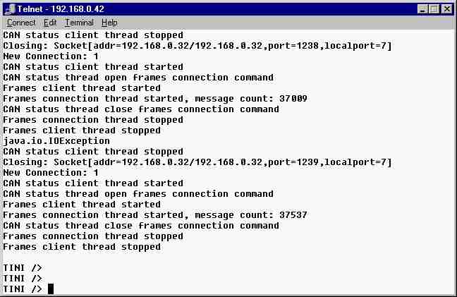
When the client connects, the number of current connections is checked. Figure 4, line 3 shows this is connecting client number 1. At this point the client connection is accepted, a new thread of control is started and a CAN frames connection is instantiated. As soon as the client requests to forward CAN frames, both a frames client thread (line 6) and a frames connection thread (line 7) are started for reception and transmission of CAN frames over the TCP/IP connection. The current number of CAN frames received thus far by the CanBusInterface from the CAN bus is also shown on this line (37009 CAN frames). From this moment on all CAN frames on the CAN bus are forwarded to the client and the client may transmit CAN frames to the CAN bus. When the client wants to stop CAN frame forwarding, a close frames connection command is issued on the status connection causing the Can Monitor server to close the CAN frames connection (lines 8, 9 and 10). At last, the client disconnects completely, which is detected by the server though a status send exception (line 11). The server then closes the session by stopping the client status thread of control (lines 12 and 13).
From the TCP/IP address information of the status socket the information can be retrieved that this test was executed on a local ethernet section (192.168.*.*) between a personal computer and the TINI board connected to a stationary CAN bus segment.
The reason for creation of separate threads of control for the reception and for the transmission of status and CAN frame connections is that each receiving thread is blocked while waiting for data for the client.
The Can Monitor client is a graphical java application running on a personal computer with classes that maintain status and frame connections with the server application on the TINI. A screen dump of this application is depicted in figure 5.
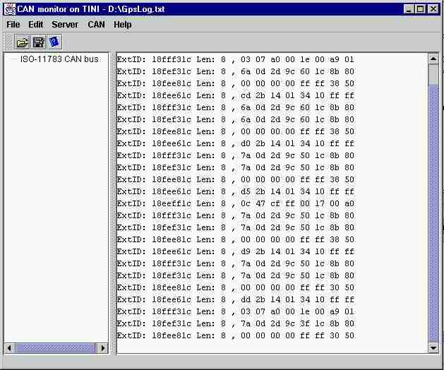
The right pane of the Can Monitor client application shows a log of the CAN frames received from the server. In this example, the CAN frames were transmitted by a GPS receiver and contain position and GPS status information. Five different parameter groups can be distinguished in this CAN frame log:
The information of each parameter group is encoded in eight bytes, the maximum length of a CAN frame. In this example log, the GPS receiver sends updated information (four CAN frames) once per second. The Name of the Electronic Control Unit was requested by the Can Monitor Client. A request consists of sending one CAN frame from the client to the server on the TINI and results in a response from the CAN bus participant which is transmitted back to the Can Monitor client. A specialized client for a specific implement or module on the CAN bus could further process these CAN frames and present the data in a more user friendly format, for example as a graphical line of a parameter against a time axis or as an X,Y plot for the GPS position measurements. The classes of the Can Monitor client responsible for the connection to the Can Monitor server are listed in Appendix B.
This pilot implementation demonstrates the capability to connect over a TCP/IP network to the CAN bus of a stationary implement. Analysis of the forwarded CAN frames as depicted in figure 5 showed that data is correctly transmitted between client and server. Expansion of the CAN bus with other components of the sugar beet harvester and fertilizer spreader was possible. For example decoding of the CAN frame that contains the name of the CAN bus participant yields:
The extended identifier of the CAN frame ExtID is 18EEFF1C and consists of four bytes:
The data field of this CAN frame is 8 bytes long, the decoded information is:
These name settings correspond to the information stored in non-volatile memory of the GPS receiver connected to the stationary CAN bus.
The implementation of a Can Monitor client / server application for the TINI was one method to make agricultural implement control accessible through internet. For specific applications like tracking of implement positions or logging of application rates more dedicated applications can be created. The pilot implementation did not make use of applets to enable a webbrowser to access the agricultural implement. However, the server part of the CanMonitor can be accessed by a client applet in a similar way as the Can Monitor java application connects to the server. In that case the TINI is used both as a webserver and an application server. In order to reduce the processing requirements on the (lightweight) TINI platform the current solution of a Can Monitor server application was chosen.
Processing power of the TINI is still a limiting factor in this pilot implementation. At high data traffic rates on the CAN bus, the can monitor client is not capable to show all received CAN frames in the output log. A possible alternative in that case is to use a specialized client that just logs CAN frames or applies a filter to just show CAN frames of a specific CAN component or parameter group. Another option to reduce traffic over the TCP/IP connection is to enable CAN frame filtering in the server application on the TINI. A client can then request the server to only forward CAN frames that match a specific pattern in the CAN frame identifier.
Issues only partly addressed in this pilot are safety concerns and reliability of the data transfer of TCP/IP. Forwarding CAN frames over a TCP/IP to the CAN bus offers the possibility that external process influences implement operation. Of course this was intended as stated in the introduction but in the case of a connection to a vehicle guidance controller or to a chemical applicator implement, erroneous data can have very unwanted effects. For this reason, in the pilot application a client initially just opens a status connection to monitor status of the CAN bus and does not allow forwarding to CAN frames. After a form of authentication the server application connects back to the client to open a different CAN frames connection. This method should be expanded in a real application to also monitor integrity of the CAN frames send over the TCP/IP connection.
The implementation of the Can Monitor server application showed that the TINI hardware is accompanied by a good Java Virtual Machine. Comparison of the client classes running on the TINI with the server classes that are executed on a personal computer reveals that most of the java.net classes behave similar on different computer platforms. The result is that the objective of the java language to create portable software in this case succeeded. The drawback, a slower execution of java byte code on the TINI hardware when compared to a cross compiled application specific for the 80C390 controller could not be verified but might be interesting to explore.
last updated: 2001-01-15